Low(no) budget
Simple Spectrum Analyser |
Last update 27 sept 2004 |
Low(no) budget
How did this project started life:
After reading some articles on the internet about creating cheap spectrum analysers using simple electronics I got interested in this subject.
Since I find it exciting to know what type of different signals are being transmitted
and on which frequency.
This was a subject that has always been of interest but the profesional equipment
is way beyond my reach.
This low end solution was good enough for me. But the problem was could i get
all the parts needed to create such a device.
Then one day when cleaning up some stacked electronics I fond some interresting
and essential parts.
At first I was planing on making it with a digital TV tuner wich is controled
via a I2C bus but I did not have one of those I could always use it as practice
on makeing my own car radio (near future plan).
I had found a project I made from a well know electronics magazine Elektuur.
It was a radio tunable from 48Mhz until 860Mhz using a standard TV Tuner.
This design used a analog voltage to control the tuning freqency and after a
couple of days thinking on how ik could hook this thing up to my Scoop. I came
up with a simple solution to get a first attempt.
How does it work
I Would use my functiongenerator to create a sawtooth signal 20Hz which with
a DC offset would be fed into the tuning pin of the tuner. The width of the
sawtooth would represent the frequency band scaned. This same signal but now
only the AC component would be fed into the Scoop to act als the X-deflection.
The signal used to reflect the signal strength (Y-deflection) is the AM signal
that came out of the mixer.
In the project there was a AGC circuit present to get better tuning. This was
set to a fixed value to avoid signal changes due to counteractions taken by
this circuit.
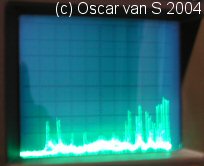
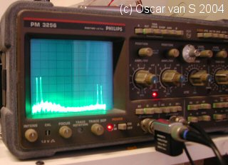
The Result:
|
And this picture is to give u some idea of how it then looks like on
a Scoop. Now that I know the concept works, special circuits will be designed
to create the propper signals to control the Tuner. Then the full range
of the tuner can be selected. |
 |
Finaly a picture from the circuit board of the tuner that produced the pictures
above.
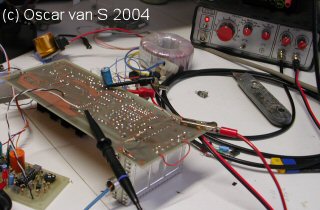 |
To the right
you see the function genrator. The transformer is used to feed the tuner circuitboard. |
More to come.......