The hardware will consist out of a micro-controller with a minimum of additional integrated circuits and as little as possible conventional electronics. It will contain a power-supply to accept a wider range of input voltages. It will also provide an interface with a RS232 serial port. The display itself will consist out of 768 LED's arranged in an array of 96x8. On this display 16 complete characters can be displayed at a time when using a font size of 8x6 (including character spacing, the actual font size will be 7x5).
The software will have to take care of reading out the RS232 interface and storing the received message in to memory. It also will have to take care of updating the complete display by means of multiplexing. This has to be done in a rate that it is not blinking for the human eye (minimal 30 whole displays per second). The software will have a minimal amount of checks to reduce the number of instructions used.
The hardware for this project was the main reason to start this project . I thought that is might be possible to create a LED sign just by using one single micro-controller and adding some extra electronics.
The micro-controller that I wanted to use was a PIC16C84 from Microchip
This controller is a 18 pins 8-bit RISC micro-controller with the following characteristics
• Only 35 single word instructions
• Operating speed DC - 10 MHz
• 1K EEPROM program memory (words)
• 36 general purpose registers (SRAM)
• 64 Bytes EEPROM data memory
• 13 I/O pins with individual direction control
• 8-bit timer/counter with 8-bit programmable prescaler
• Low power consumption < 2mA typical @ 5V, 4MHz
By choosing this controller I also set the limitations because I did not know if the whole program would fit in the 1K of program memory or if it was fast enough to update the screen as often as I wanted. Also the EEPROM size is not very large which limits the sentence to be displayed. Although 63characters is acceptable.
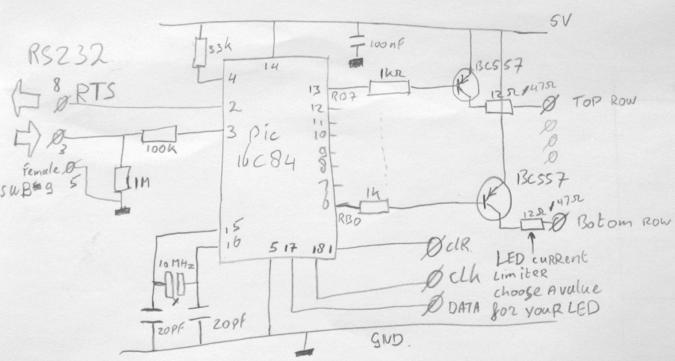
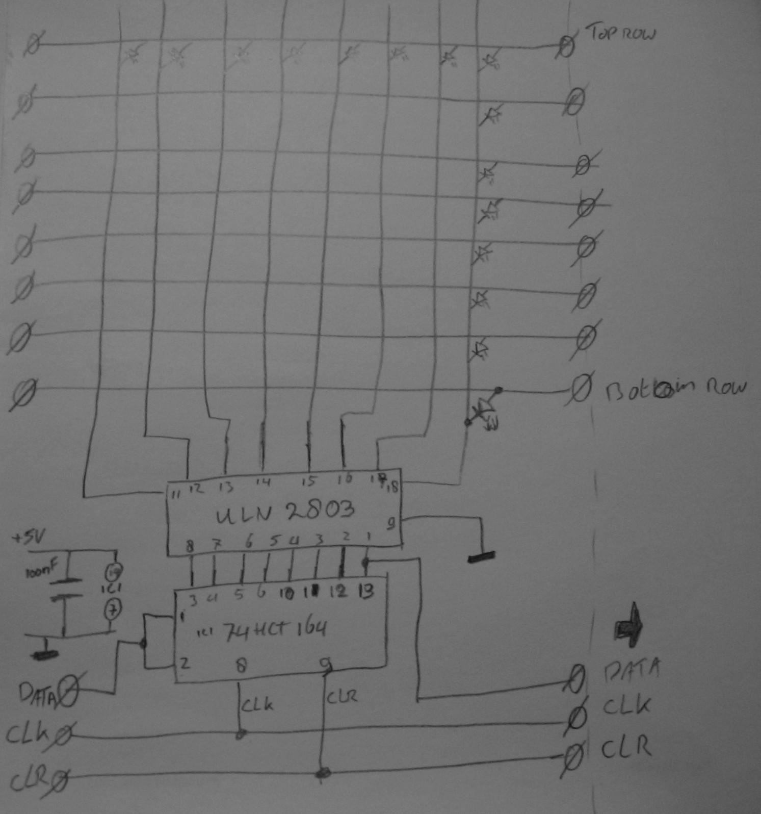
The controller circuit and one Matrix Segment, add as many as you want I have 10 of them.
Because we want every LED to be controlled separately we need 8 + 96 I/O lines, this amount is not available so we use a shift register to create 8 datalines using only one input line and 2 control lines (clock & reset). By extending this idea we can create the 96 I/O lines needed for the columns. By using the shift registers we now need 8 + 3 I/O lines and this amount is available on the micro-controller.
The RS232 interface is realized by using a simple resistor to limit the voltage and one resistor the pull the line to GND when it is not connected.
The RS232 interface usage voltages ranging from 12V to 12V. The -12V is a 1 also called (Mark) and the 12V represents a 0 (Space).
By using a resistor we reduce the 12V to a GND level (0) and 12V will be limited to the power-supply (1). This is done making use of the internal characteristics of the input pins of the micro-controller. The only disadvantage of this is that the value of the data is received in an inverted state. To ensure that the data is read correctly the software that reads out the serial information will have to correct this.
The software will consist out of two major components. One will take care of updating the screen with the information out of the internal EEPROM and the other will check the serial line for activity and read the incoming data from that line in to the EEPROM.
The screen routine will be programmed using an interrupt driven event. This is done to ensure a correct number of updates per second, which is needed because else the display will blink for the human eye.
In the spare time that the screen is not updated this routine is looking at the serial line to detect if a transmission is started. If it detects a signal it will do checks to ensure it is a signal and will then continue receiving bytes until a stop byte is received. If the received character indicates the start of a transmission it will send the OK message so that the other side can start transmitting its data to display. During this it will wait for the end of transmission sequence.
All serial transmissions are done using 4800bps 8databits 1 stop bit and no parity.
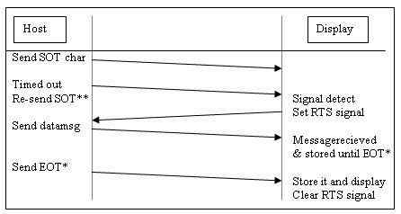
** SOT = Start Of Transmission
* EOT = End Of Transmission
As mentioned does the system use the RS232 interface, it uses this to receive the data it needs to display.
This data is stored in its internal EEPROM.
Because the size of the EEPROM is limited the number of characters stored is also limited to the maximum amount minus 1 for the termination character.
This number also includes the special function commands. They are also stored in the same EEPROM.
There are 2 types of commands one that appear before a sentence and one that comes after a sentence.
These two types are needed because of the way the data is read and then needs to be interpreted.
The command before the sentence determines how the sentence comes into the screen and the other defines how it leaves the screen.
The following commands can be used. (future development)
Start command * |
Exit command * |
||
Shift |
0x01 |
FADE OUT |
0x12 (18) |
FADEIN |
0x02 |
SCROLL OUT UP |
0x13 (19) |
SCROLL IN UP |
0x03 |
SCROLL OUT DWN |
0x14 (20) |
SCROLL IN DWN |
0x04 |
SPLIT OUT UPDWN |
0x15 (21) |
MERGE IN UPDWN |
0x05 |
HOLD |
0x16 (22) |
|
|
BLINK |
0x17 (23) |
*Note: ALL of these start and exit commands have not been implemented in the source code.
Special characters that mark the end of a sentence.
Description |
Hexadecimal value |
Line Feed \n' |
0x0A |
Carriage Return \r' |
0x0D |
C string delimiter |
0x00 |
The system will consist out of hardware components and a software package to control this hardware.
The hardware will exist out of a micro-controller, power-supply components, buffers, shift-registers and a custom-made matrix display containing 768 LED's (96x8)
The software for the micro-controller has to take care of the following things.
• Initial initialization
• Receive data from the serial input and store them in its internal EEPROM
• Read out the EEPROM and show the contents on the matrix screen.
To do all this the following sub-components will be defined.
Initialization routine:
• InitializeI/O
• SetInitialRegisters
• SetTimer
Serial In routine:
• StartOfMessage
• RecieveByte
• DetectEndOfMessage
• StoreByte
Screen Update routine
• SetRegisters
• ReadEEPROM
• LoadColumn
• LookUpInCharTable
• ShiftDisplay
• DisplayReset
• SetRegistersForCommand
Besides these components there will be on more component and that will be the character lookup table.
This table will hold all the characters that can be displayed on the screen. This table is also the main conversion between the ASCII characters stored in the EEPROM and the character shown on the screen.
Each character is made up of 6 bytes because the characters will be 8 bits in height and 6 bits in with.
This character table will be stored in program memory since there is no other place available that is large enough.
The table will hold all ASCII characters from 0x20 until 0x7F. That is 96 characters times 6byte is 576 bytes of memory for just the character table. This is a huge reduction of the available program memory because the controller has only 1024 14bit words of program memory.
This describes the interface between the hardware and software.
We can see that there are different blocks
The oscilator circuit.
The serial interface that communicates via the RS232 protocol and uses a Ready To Send signal to indicate that the unit is ready to receive data from the host.
The data lines that control the array of shift registers. And the 8 data lines that control the actual lighting of each LED.
Here an overview of all the IO pins that are on the microcontroller.
Pin |
|
Pin |
|
1 |
RA2 -> Clear all shift registers. |
10 |
RB4 |
2 |
RA3 -> Ready To Send signal for host |
11 |
RB5 |
3 |
RA4 -> serial in |
12 |
RB6 |
4 |
MCLR with 33K to 5V |
13 |
RB7 -> Top line of the display |
5 |
GND |
14 |
+5V |
6 |
RB0 -> Botom line of the display (underscore) |
15 |
Oscilator |
7 |
RB1 |
16 |
Oscilator |
8 |
RB2 |
17 |
RA -> Data for first shift register |
9 |
RB3 |
18 |
RA -> Clock for all shift registers |
To make all this hardware work only a power-supply needs to be connected.
This circuit can be powered with a simple 7805 power regulator so that any adaptor that can deliver a voltage between 6-16Volt DC and more than 150mA of current will do.
To ensure all the IC are working correctly make sure that you have a 100nF condenator as close as posible to the microcontroller and to all the shift registers.
Available code: (use the save as option in your browser to prevent it from showing it in the browser window)
sourcecode: movesign.asm + chartable.inc
binary hexfile: movesign.hex
MS Windows tool to update text to be displayed.
sourcecode: sorry not available.
binary files: Server.exe & client.exe or Standalone version (fixed comport)
Good luck and enjoy building your own version.
| Warning !!! | |
| This project is not a finished product. So if u want to resuse the software or hardware ideas use it at your own risk. |